Indiana University Libraries Book Repair Manual
Post Binder
Treatment Criteria:
The post binder is a structure which is often used as a more substantial substitute for a ring binder. Materials must have substantial gutter margin to qualify. The text block either may or may not already have holes for a ring- or post-type binder. Large materials such as atlases are often candidates.
Tools Needed: |
|
Materials Needed: |
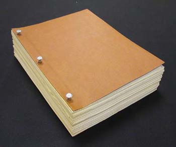 | Our example is already in a post binding, but it is in a soft cover and one of acidic paper. We will make new cloth-covered hard boards with hinges for it. Sometimes materials with solid leaves (no holes) can be converted to post bindings, and in these cases the holes can be made with a 3-hole punch or a paper drill. |
 | As mentioned above, it should be determined that the material has sufficient gutter margin for this treatment, especially if it is being converted from a different binding structure. As a rule, 2.5 cm (1") is about the minimum. |
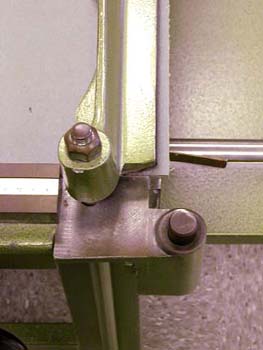
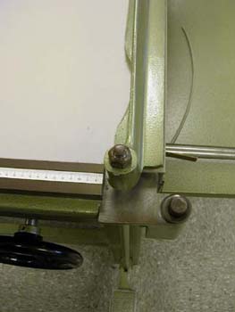
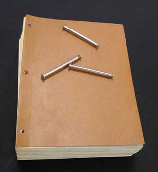 | First, the old posts are removed. |
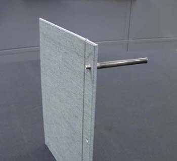
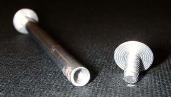 | Here is a look at how the posts work. As you can see, they are tapped with bolt threads and simply screw together. They are 1/4" in diameter and are available in a variety of lengths, from about 1/2" to 3." Also available are ¼" and ½" extensions. These can be had in aluminum or brass. |
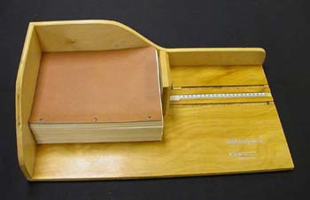 | The length of the book is measured using the MEASUREpHASE, and to this measurement 8 mm is added, to allow for 4 mm of square at both the top and bottom. This amount of square is more generous than the usual 3 mm because the edges of the text block's leaves are uneven. This is due to slight variations in the locations of the holes, rather than to varying dimensions of the leaves. Because of this, trimming the text block in the guillotine while it is out of the binder will not align the edges flush when the structure is reassembled, so we compensate by adding an extra millimeter of square. |
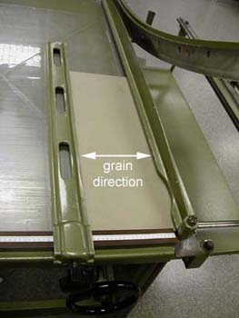 | Moving to the board shear, a piece of board is cut to the length measurement arrived at in the previous step. The grain direction is oriented as shown in the illustration. Ideally, the width measurement of the piece is sufficient to yield two widths of the book plus 8 mm. If not, it can be done in more than one piece, but cut all the board needed to yield these pieces now, before the fence is moved. |
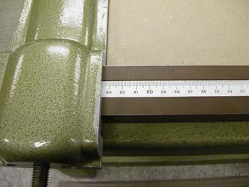
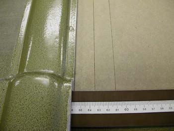
 | We now need to cut two 2.5 cm wide pieces from this board. These will be the hinge stubs. This is done easily and accurately by the following means. First, move the fence to the far left of the bed (or remove it). Turn the board 90 degrees from the previous illustration. Place the board on the bed of the board shear and situate it so that the long edge is agaist the rule and the edge on the right is flush with the cutting edge. Nudge the fence up against the board and move to the right until the first even measurement is reached. In this case, that is 66 cm. |
 | This leaves only a few millimeters overhanging the edge, |
 | This scrap is cut off, and the board is flush with the cutting edge. |
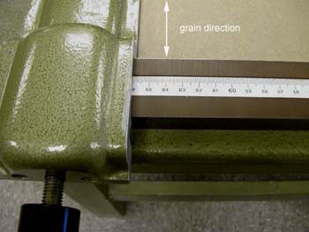
 | The fence is now moved 2.5 cm, to 63.5 cm, and the board is cut again. |
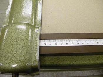 | The fence is moved another 2.5 cm, to 61.0 cm, and the board is cut again. |
 | If we back up to the first fence location, we see that this yields two pieces, each 2.5 cm wide. |
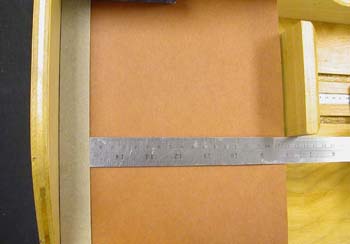 | The book is placed in the MeasurePhase, in the position used for taking the width measurement. One of the 2.5 cm pieces of board we just cut is placed against the back wall and the measurement is taken from its front edge. |
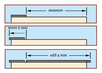 | To this measurement is added 4 mm for the square at the fore edge. Two pieces of this width are cut from the piece(s) of board previously cut to finished length. As you can see in the drawing, the hinge stub will be moved spineward by 2 mm to provide only 2 mm of square at the spine edge. |
 | Now a leaf is placed on the hinge stub, 2 mm from its spine edge and centered vertically, 4 mm from each end. As shown here, it is often a good idea to go a few leaves into the text block to get the one used for this pattern, as the spine edge will normally be sharper and less worn than those of the outermost leaves. |
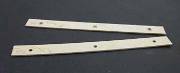
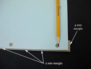 | The locations of the holes are transferred to the hinge stub by means of simply tracing them with a pencil. Only one of the stubs needs to be marked. The respective outer margins are shown in the illustration as well. |
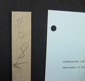 | It is wise to mark both the lateral and longitudinal orientation of both hinge stubs at this time. In this case, "H" indicates the head end; "S" the spine edge. |
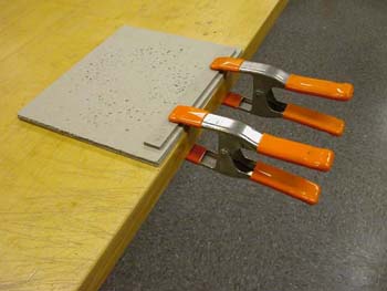 | The hinge stubs are aligned flush and properly oriented, then fastened by some secure means to a solid surface such as a table or bench top. Here we are using spring clamps. C-clamps also work well. The stub bearing the tracings of the holes is situated on top with the marks showing. A pad made of several thicknesses of board is placed under the work to protect the table or bench top. |
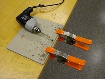 | The holes are drilled according to the marks we traced from the leaf. A ¼" diameter bit is used. |
 | Here are the drilled stubs. |
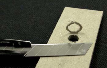 | An embossed area of compacted board usually raises up around most of the holes, This is easily trimmed off with the razor knife. |
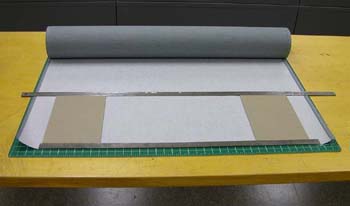 | The cloth is now selected and cut to a length 5 cm in excess of the length of the boards, to allow for a 2.5 cm turn-in at both the top and bottom. |
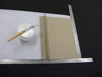
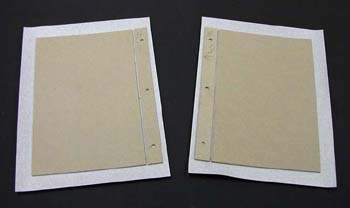
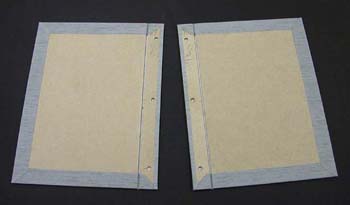
 | The selvage is cut off square at both ends and the first board is glued to the cloth, 2.5 cm from the top, bottom, and end of the cloth. The adhesive used is PVA mixture, which is applied to the board, not the cloth. |
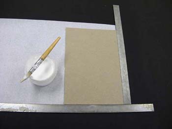
 | The corresponding hinge stub is glued to the cloth and is spaced 1 ½ board thicknesses away from the board using a template of that thickness. Attention is paid to the orientation of the stub. |
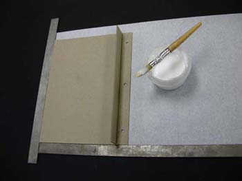 | The same procedure as above is followed to create a mirror image of the first board/stub assembly. |
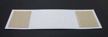 | Here we can see that the front and back boards were accommodated by one piece of cloth, which makes it easy to keep the mirror imaging orientation on course. But of course two separate pieces will work just as well. |
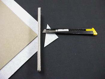
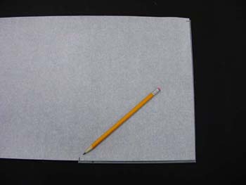
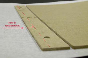 | The turn-in at the spine edge doesn't need to be as wide as the 2.5 cm most commonly used. It only needs to lay over on the stub about 5 mm. So, adding the thickness of the board, measuring 7 mm from the edge of the stub is normally about right. |
 | All edges are now trimmed to size. |
 | The corners are trimmed at approximately a 45 degree angle, 2 board thicknesses out from the board/stub corners, using a spacing template of that thickness. |
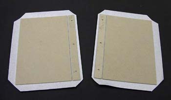 | With the corners all trimmed, we are ready to glue down the turn-ins. |
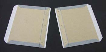 | We begin with the top and bottom. Once the cloth is down, it is worked rigorously into the hinges with a bone folder. |
 | Now the side turn-ins are glued down. |
 | A piece of cloth is cut for each board, measuring 2 mm shy of the boards' length and width. |
 | These pieces are glued down as nearly as possible to 1 mm from all edges. |
 | The holes are located, and now we need a hollow steel punch (the one we use for phase boxes). |
 | The punch is pushed through the cloth on the top side of the board, turning it as it is pushed through so it cuts the cloth. |
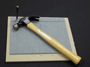 | The board is placed on a protective pad of scrap board and the punch is hammered through the cloth on the underside. |
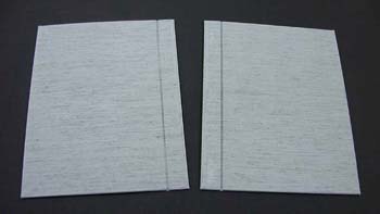
 | The punch can be turned in the hole, then the same done from the opposite side, to ream it to a nice clean opening. The boards are finished. |
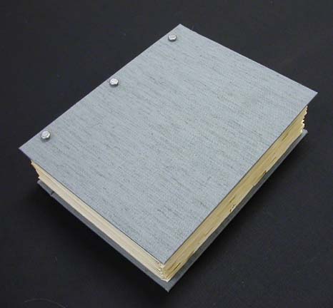
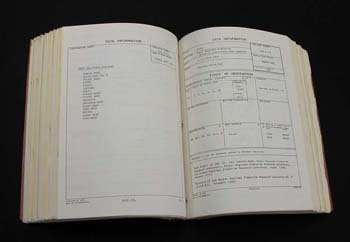
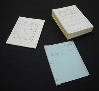
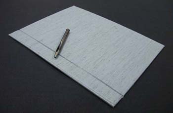
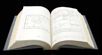 | The posts are re-installed, and the only thing remaining to be done is to affix or re-affix any labeling, such as the call number label or barcode. Here is the finished book in open position. |
 | And here it is shown closed. The book is ready to circulate again. |